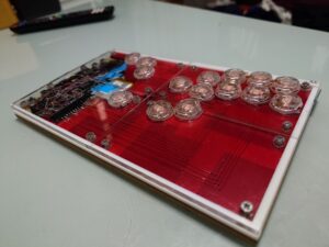
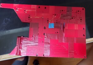
DIY Wireless Leverless Arcade Controller for Steam & Switch Using 100-Yen Store Parts (Part 2: Layout Design & Acrylic / Case Fabrication)
 Admin
Hello everyone! Welcome to Part 2 of my DIY wireless leverless controller build series. In this post, I'll walk you through the process of fabricating the raw materials to bring the enclosure base to life.
Here, I'll cover everything from the layout design prepared in Excel to drilling holes in the acrylic top plate, followed by fine-tuning each component using real-world mockups.
1. Meticulous Layout & Dimension Design in Excel
Before jumping into fabrication, I started by simulating the button layout and dimensions in Microsoft Excel.
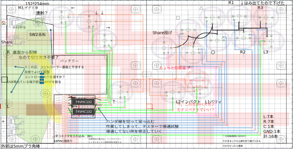
In addition to button placements, the diagram covers routing paths for the matrix wiring (16 lines in total), dedicated space for the logic IC (74HC132), and visual clearance checks to ensure the battery and PCB wouldn't interfere with anything.
The crisscrossing pink lines across the blueprint also serve a specific purpose: planning ahead for the final paint job—a geometric pattern inspired by Tomoyasu Hotei's iconic guitar. I calculated these geometric lines right from the design stage so they could both route and secure the enameled magnet wire while doubling as masking lines during the painting phase.
A quick note on the IC placement space:
I originally reserved space in the lower-left corner for the SOCD cleaner logic ICs. However, as the 3D assembly progressed, clearance issues forced me to relocate them elsewhere. I'll share how that physical trial-and-error turned out in the final chapter covering circuit implementation.
2. Drilling Acrylic with a Water-Cooled Step Drill Bit
Once the Excel design was complete, it was time to dive into drilling the 22mm button holes into the acrylic top plate.
While acrylic offers a gorgeous, glossy finish, it's notorious for cracking instantly if you drill straight into it due to frictional heat and the bit catching. To overcome this, I built a makeshift 'water-cooling setup' to keep the drill bit constantly submerged while cutting.
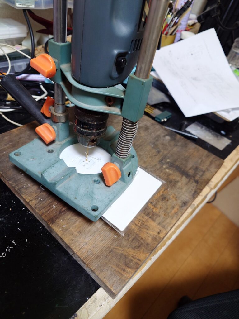
The drill and drill press stand
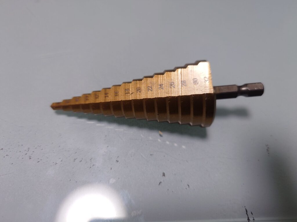
I bought a step drill bit (cone drill) for about 980 yen. Amazon had the best price.
For tools, I used a drill press stand to ensure straight, vertical plunging, paired with a step drill bit (unibit) to expand the hole gradually.
I cut down a small plastic bottle (an empty one-cup shochu bottle I had lying around) to make a reservoir, secured it onto the acrylic plate, filled it with water, and went to work.
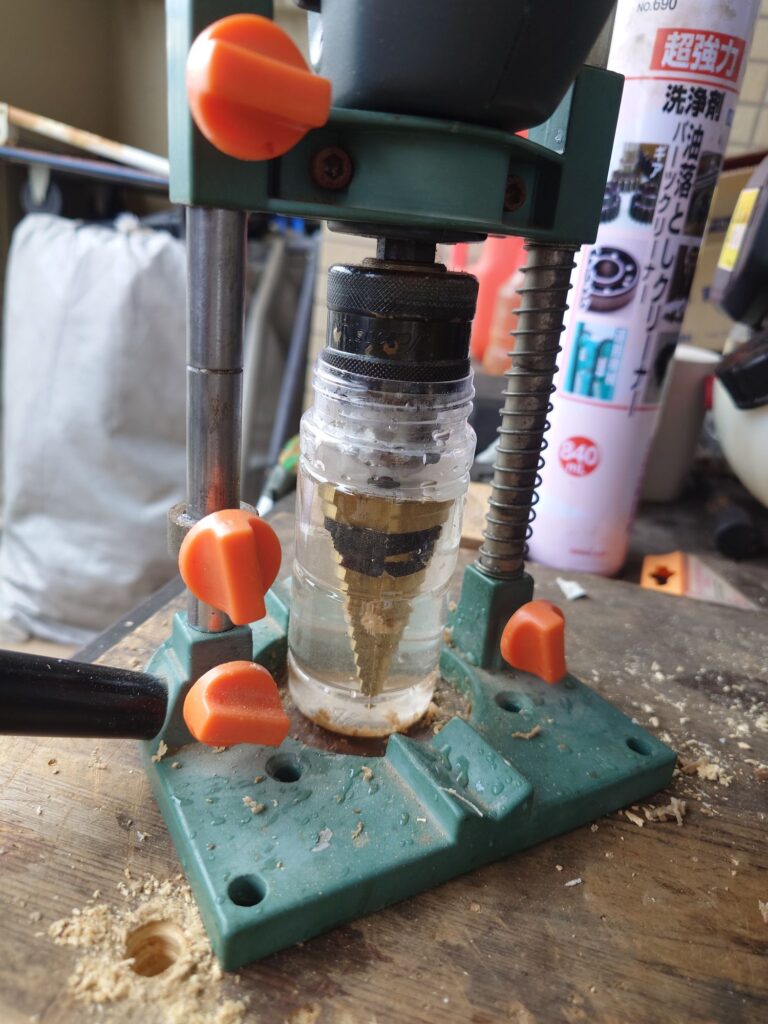
Even at lower drill speeds, heat builds up quickly, so patience is key. I paused and replaced the water four times while widening the hole to 20mm, and an additional five times just for the final step to 22mm, shaving away tiny increments while keeping the work area chilled. Thanks to this incremental cooling, I drilled clean, perfect circles without cracking a single sheet.
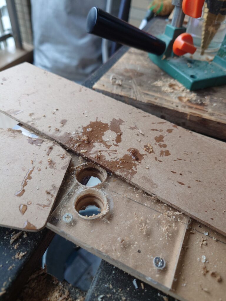
To prevent breakout cracking on the back side as the bit punched through, I clamped a piece of scrap MDF underneath as a backing board. However, the step bit also had to drill through the dense MDF backing, which added resistance, and MDF dust mixed with slightly melted acrylic particles, making cleanup a bit tedious. For my next build (#2), I plan to test removing the backing board just before the final punch-through step.
3. Validating the Build Process with a 1/4-Scale Prototype Using Real Parts
Rather than jumping straight into full assembly after drilling the main top plate, I started with a partial1/4-scale prototype test piece to evaluate and verify the conceptbefore moving any further.
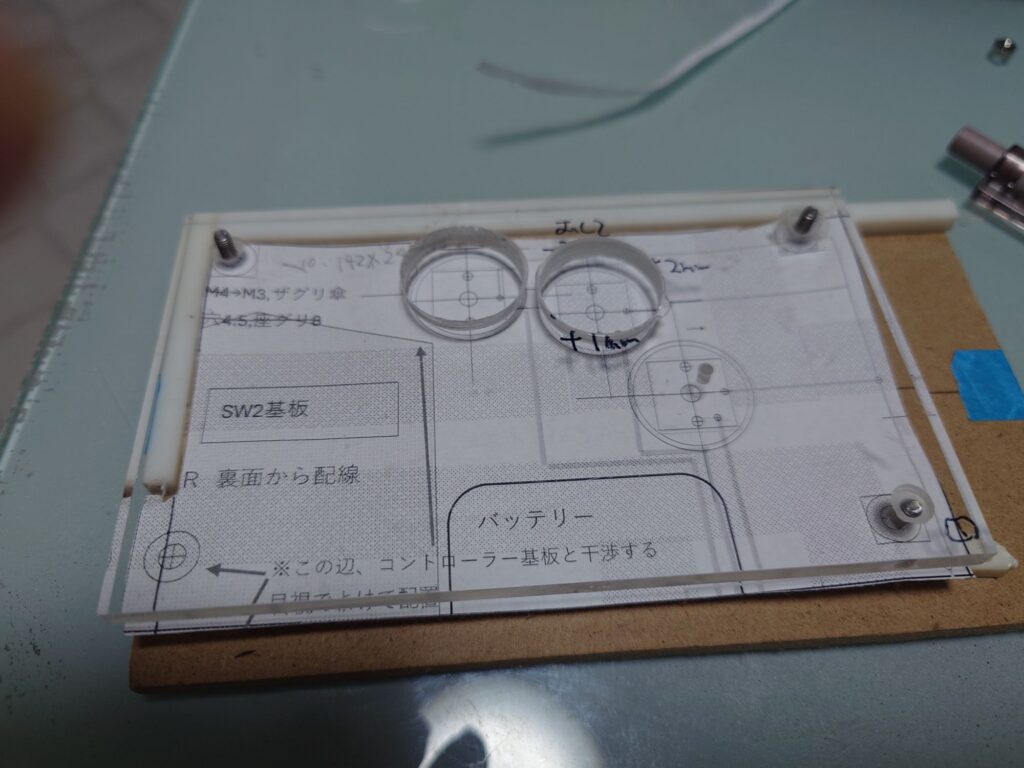
At this stage, I assembled the test piece and used the button cap profile as a guide to rigorously verify real-world clearances, making sure there was no catching, binding, or wobbling when pressing the buttons.
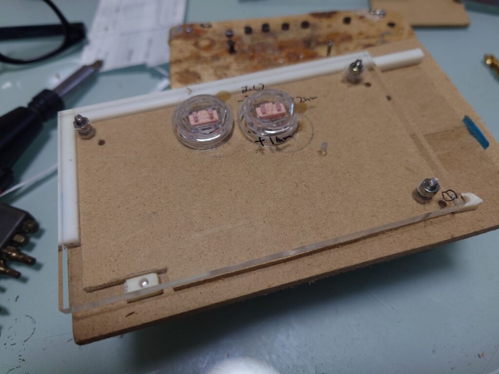
I'll cover the electrical details in the next post, but here I drilled pin holes and locating holes for the switches to ensure the buttons actuated properly. The plastic square rod pillars also let me check the clearance between the button caps and the top acrylic plate. Evaluating the tactile feel confirmed it worked just as intended—a complete success.
The switches I used, Kailh Low Profile V1 Pinks, feature unique arcade-style pin placements with practically zero tolerance for error. Through this physical mock-up, I determined that the outer structural walls (pillars) needed to change from the originally planned 5mm square rod to a stacked pair of Tamiya 3mm hollow plastic square rods (6mm total), providing the data needed to optimize the interior space and dial in the clearances.
4. Stacking & Centering on the Final Panels
With the outer frame thickness and clearances confirmed via the prototype, I moved on to machining the final panels: 3mm-thick MDF (sourced from a Seria clipboard) and acrylic sheets.
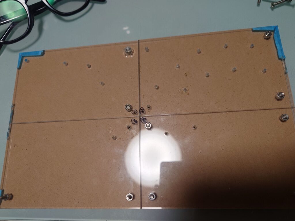
To prevent even a millimeter of misalignment between the acrylic and MDF panels, according to the Excel layout,I first drilled M3 screw holes at the four corners and reference points, screwing them firmly togetherto clamp the stack securely. I also countersunk the mounting holes so the screw heads would sit completely flush.
With the layers locked into a single solid unit, I drilled 2mm pilot holes through the center points of each button to mark the precise centers on the production board. From there, I applied the water-cooled drilling technique to cleanly bore out the large button holes across the final panel.
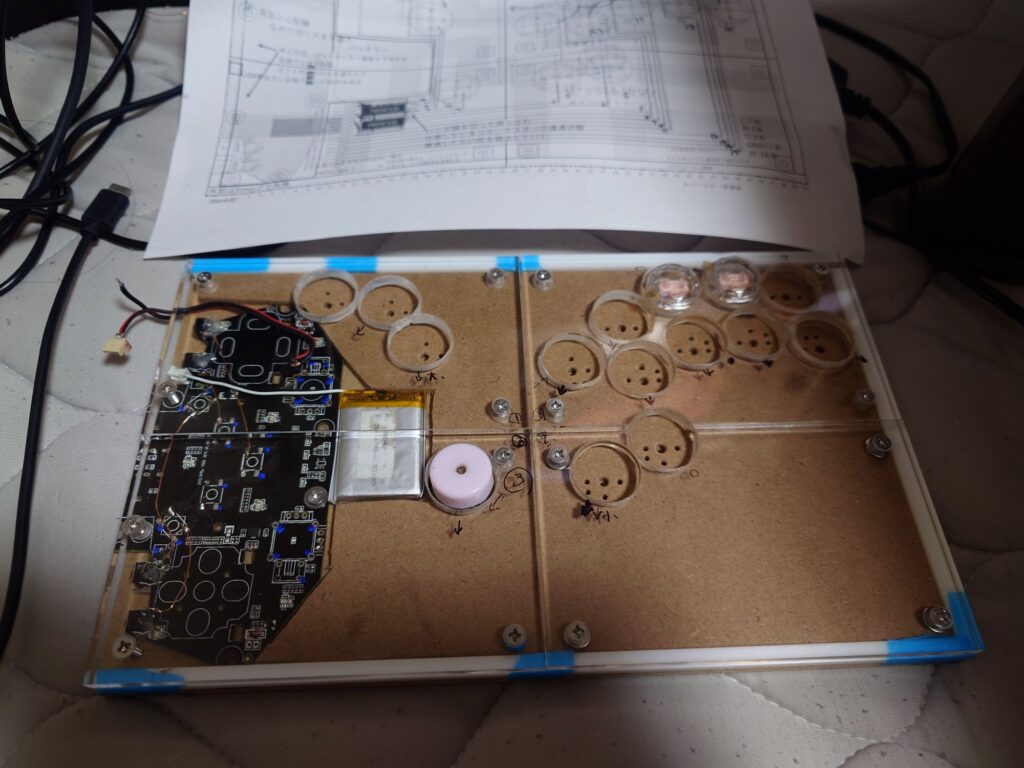
And with that, the enclosure base fabrication was complete.
Next time, we tackle the true heart of this project:"Solderless Brass Tube Crimping & Wireless Board Wiring."I'll finally reveal my custom wiring system utilizing brass tubes from Handsman, along with photos of the DIY drilling jig for switch pins! I'll also showcase the side-button mechanism built with plastic square rods post-wiring, so stay tuned!