[DIY Leverless Controller] Building a Wireless Fight Stick for Steam & Switch Using 100-Yen Shop Parts & Key Switches (Part 3: Solderless Brass Tube Crimping & Wireless PCB Wiring)
 Admin
Hello! Welcome to Part 3 of my DIY wireless leverless controller build log.
In the last entry, we fabricated the enclosure frame and cut the acrylic top plate. This time, we dive into the project's biggest technical highlight: the wiring.
Our theme today is a proprietary "solderless brass tube crimping method" designed to minimize soldering to the absolute bare essentials.
Inspired by the PS3 Controller: As Long as It's Electrically Connected, It Works
When wiring up our key switches (Kailh Low Profile V1), I wanted to maximize build efficiency, so I devised a solder-free crimp-fit system to connect directly to the pin sockets.
The spark for this approach came from the stock PS3 controller. If you have ever disassembled one, you know its internal circuit board relies heavily on pressure-fit contacts everywhere.
"As long as solid electrical contact is maintained, that's all that matters."
Inspired by that practical philosophy, I bought long brass tubes (2mm outer diameter, 1mm inner diameter) at Handsman to mass-produce custom crimp sleeves sized exactly to the thickness of my MDF board.
Mass-Producing Brass Sleeves with a Diamond Cutting Disc
First, I needed to slice the long brass tubing into a large batch of sleeves measuring just under 3mm to match the 3mm thickness of the internal board.
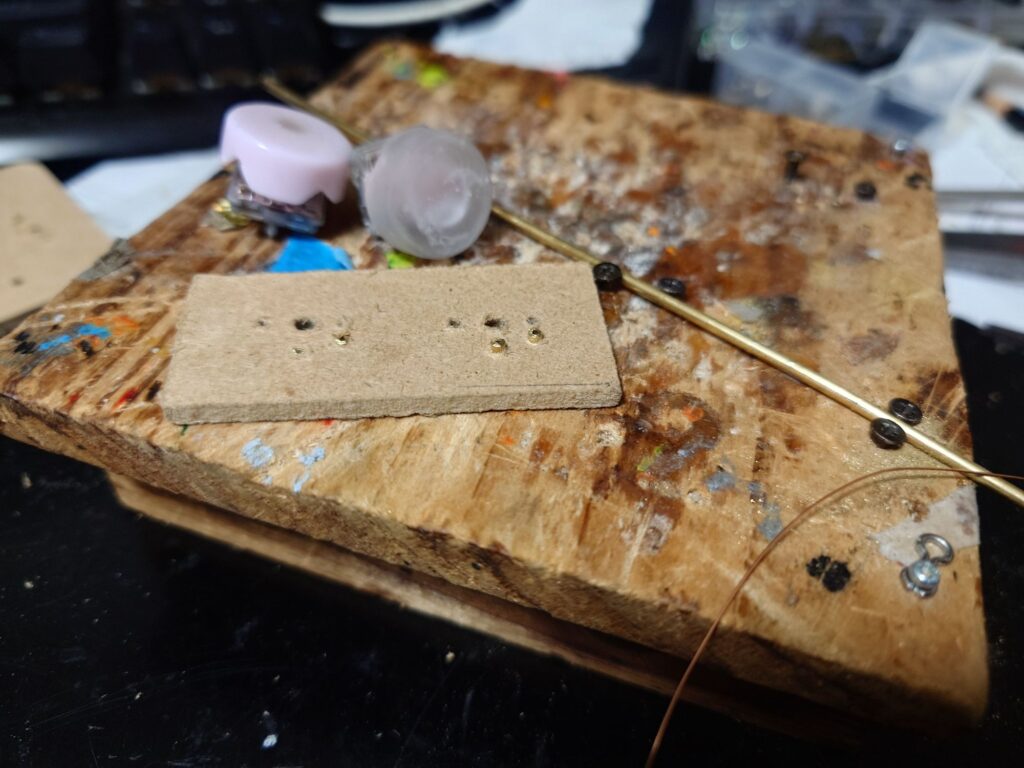
For cutting, I mounted a 100-yen rotary diamond cutting disc onto an electric drill. I made a simple cutting guide by drilling a hole through a wooden scrap block, fed the brass tube through, and pressed lightly by hand as I cut. This kept wobble to zero and allowed fast, consistent mass production.
Sanding each tiny piece individually would have taken forever, so I applied another handy trick: I drilled multiple holes in a piece of wood and slotted about five cut brass tubes in at once. Then I ground their tops down together using a metal file, evening out their lengths while deburring and squaring off the edges in mere seconds.
It was painstaking work... Next time, I might just cave and buy pre-made pin sockets!
Solderless Mechanical Crimping: Trapping the Magnet Wire
With the brass sleeves ready, it was time for initial wiring and continuity testing.
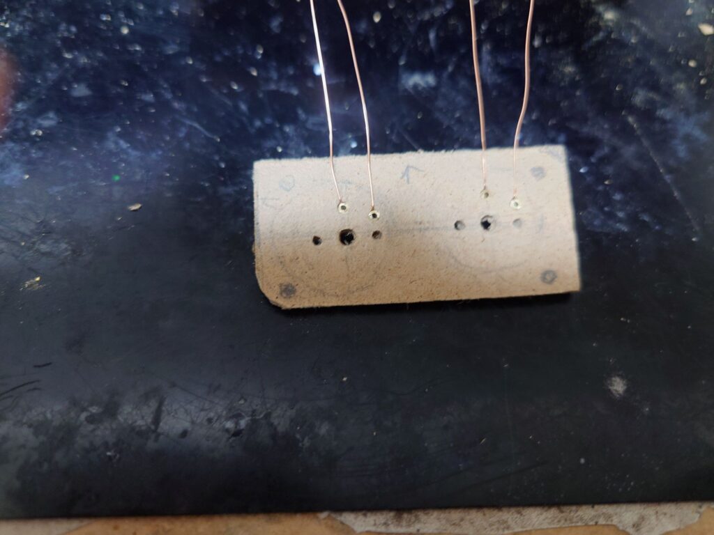
The procedure is remarkably simple yet dependable:
- Burn the tip of the 0.32mm enamelled magnet wire with a lighter to strip the insulation and expose bare copper.
- Thread the magnet wire through the switch-leg hole pre-drilled in the MDF board.
- Press one of our freshly cut ~3mm brass tube sleeves into the hole right over the wire.
Because the MDF hole and the outer diameter of the brass tube are calibrated to an ultra-tight interference fit, simply pressing the sleeve in locks the magnet wire tightly into the seam, holding it with tremendous grip.
Final Continuity Testing with Buttons Installed
Once the sleeve anchoring structure was established, I performed a final continuity test with the acrylic top plate and actual button caps (Cosmic Noise 20.8mm) fully assembled.
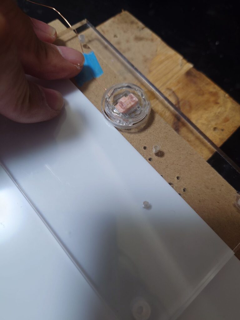
Even under repeated, forceful button presses, the brass sleeve held the key switch pin and the magnet wire firmly together with zero play, delivering 100% reliable continuity. Without relying on specialized crimping tools—using pure friction and surface contact—this proved that the connection method could easily endure intense gaming sessions.
Slimming Down the Donor PCB: Desoldering Connectors for Direct Wiring
Next came modifying the heart of the wireless build: an unused Switch controller board that had been retired due to stick drift. To fit everything inside our ultra-slim enclosure, I ruthlessly removed any component adding vertical bulk. The internal clearance at this stage was 5mm (eventually expanded to 6mm).
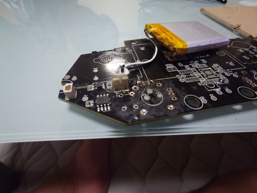
First on the chopping block were the lithium-ion battery and its bulky white plastic connector. That connector alone added several millimeters of height, so I completely desoldered and removed it using solder wick. I then converted the battery lines into a direct-soldered setup, keeping the profile as flat as possible.
Removing Interfering Front Tactile Switches
The battery connector wasn't the only height issue. The tiny tactile switches on the front face of the board (the membrane contact side) used for menu navigation posed another major hurdle.
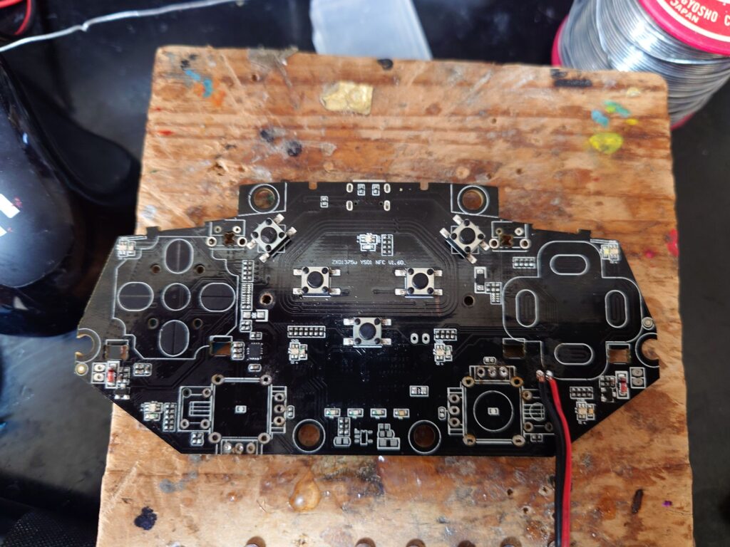
Because their raised profiles physically interfered with the acrylic top plate and the internal MDF substrate, I desoldered and removed every single tactile switch from the board.
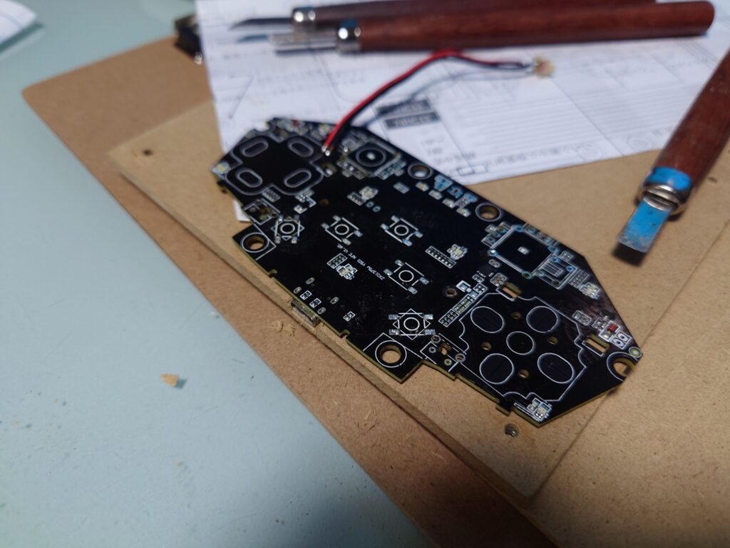
With those switches stripped away, both sides of the PCB became completely flat, primed to slip smoothly inside our layered sandwich enclosure.
Relocating Menu Buttons to the Side Panel
Of course, we couldn't just throw away the menu button functionality. For ergonomic ease, I decided to relocate them so they can be pressed from the side of the case.
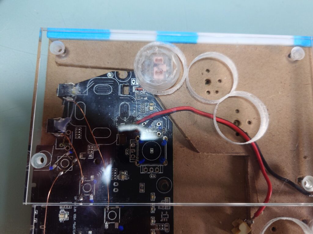
I ran ultra-fine 0.32mm magnet wires from the original switch solder pads on the PCB out to new commercial tactile switches mounted along the enclosure's side. This neatly bypassed our tight vertical clearance while creating a sleek setup where menu commands are triggered with a satisfying side click.
Cutting the MDF Board for a "Vertical Drop-In" Layout
Even with the Switch controller board and battery flattened out, stacking them directly on top of the 3mm MDF board would still exceed our enclosure depth.
To solve this, I made a bold cut into the internal MDF substrate.
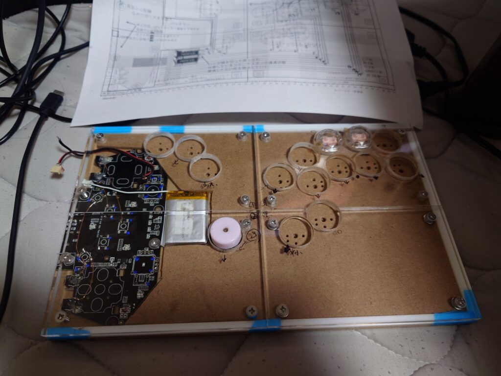
Following my Excel blueprint, I carved out a large rectangular opening on the left side of the 3mm MDF board. Using that hollowed-out pocket, I dropped the donor PCB and the lithium-ion battery in vertically, placing them side by side rather than stacked.
By recessing the parts into the board's own thickness through this custom-fitted 3D layout, I successfully packed all the wireless hardware into an ultra-slim internal clearance of just 6mm (created by stacking two layers of 3mm Tamiya hollow square plastic beams) without any physical binding.
Adopting a 20-Pin Header: A Modular Design Ready for Future PCB Swaps
With the vertical clearance issue solved by the drop-in layout, it was time to wire the interconnect between the button-side MDF board and the donor Switch PCB.
For this task, I grabbed the 20-pin male/female headers from our parts list.
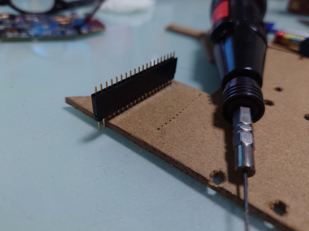
Right-angle pin headers were sold out, so I bought straight ones and bent them manually with pliers. A pen-sized electric screwdriver with small drill bits made quick work of fine-tuning the small board holes.
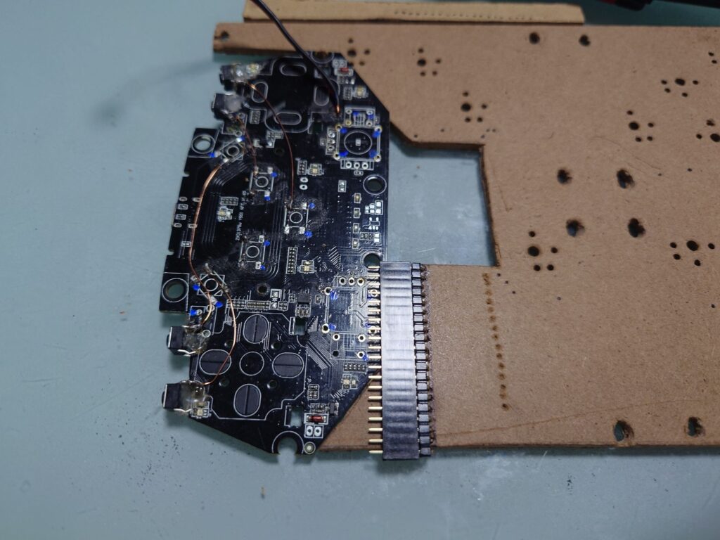
If you solder wires coming from the buttons directly to the donor board, future disassembly and maintenance become impossible. By routing everything through this disconnectable header, the MDF button assembly and the controller board can be detached in a snap. This design also allows swapping in an entirely different donor PCB (such as a PS3 board) down the road.
To match the exact number of signal lines needed,I snapped the 20-pin connector down by hand into an 18-pin configurationfor installation.
And right here, I decided to attempt another bold experiment.
I wondered if the friction-based solderless crimping that worked so well on the main buttons could be applied to this header connector too. The plan was to push stripped magnet wires into holes drilled in the MDF, then press the connector pins forcefully down on top. That way, all 18 signal lines would be crimped simultaneously without a single drop of solder... It sounded like a flawless plan on paper.
Wiring from the Donor PCB: Test Pads and a "Controlled Chaos" Aesthetic
With the interconnect position locked in on the MDF board, I began wiring up leads from the Switch donor PCB.
Fortunately, this controller boardconveniently had exposed test pads (test points) for every single button on its underside.Soldering to these pads was far easier than working with the tiny surface contacts on the front, and the pads took solder beautifully, making the work fly by.
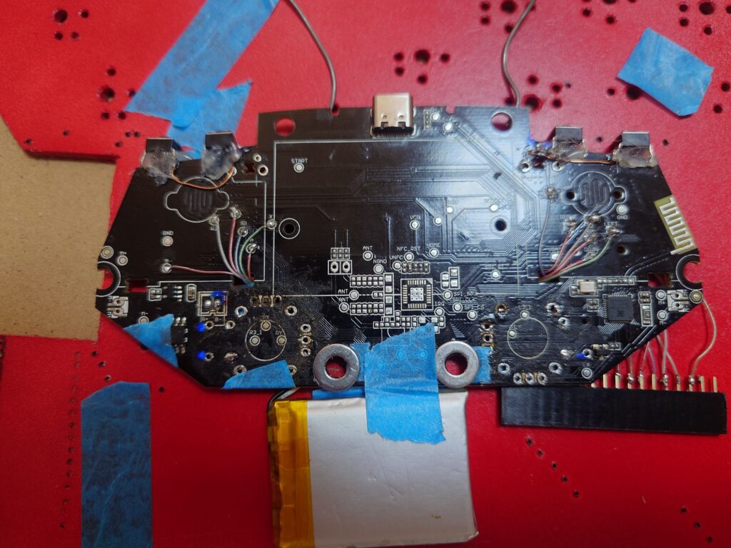
I also lightly misted the board with white primer and the Soulful Red paint from Part 1. I ended up painting and drying it between soldering sessions, so the timeline is a bit out of order—forgive the continuity jump!
For the wiring material itself, I had a specific aesthetic vision in mind.
Instead of using the clean magnet wire from the button side,I cracked open a broken, discarded Apple USB cable from my daughterand harvested its ultra-fine internal multi-colored wires to serve as donor leads. True to genuine Apple quality, the strands are incredibly fine yet resilient, and solder effortlessly.
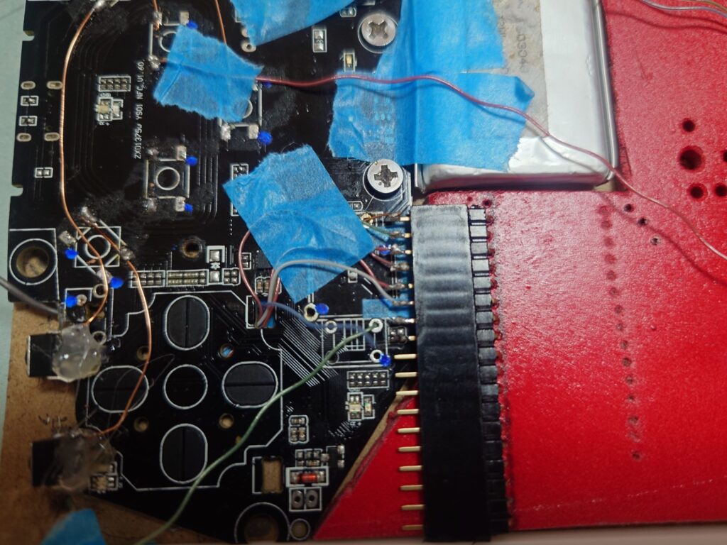
I deliberately chose these vibrant, multi-colored wires becauseI wanted a chaotic, mechanical visual reminiscent of the exposed cyborg innards in Kikaider 01.That was the exact look I was aiming for.
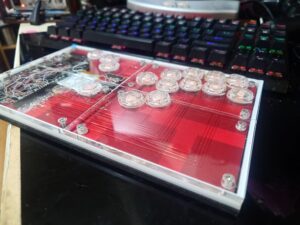
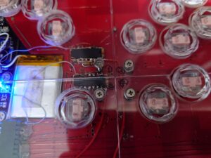
Visible beneath the clear acrylic top, the donor Switch PCB looks trapped within the chassis, as if its soul is being drained by the machine during cybernetic conversion. It captures an eerie yet stunning industrial vibe that I brought to life through hands-on fabrication.
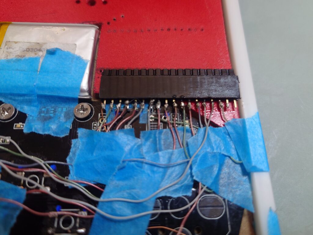
I soldered the loose ends of these wires to the corresponding pins of the 18-pin interconnect header mounted at the MDF cutout. Once all connections were verified, I potted the entire base of the connector in hot glue to prevent broken wires from vibration or repeated unplugging, ensuring top-tier mechanical strength.
Drilling Key Switch Pin Holes
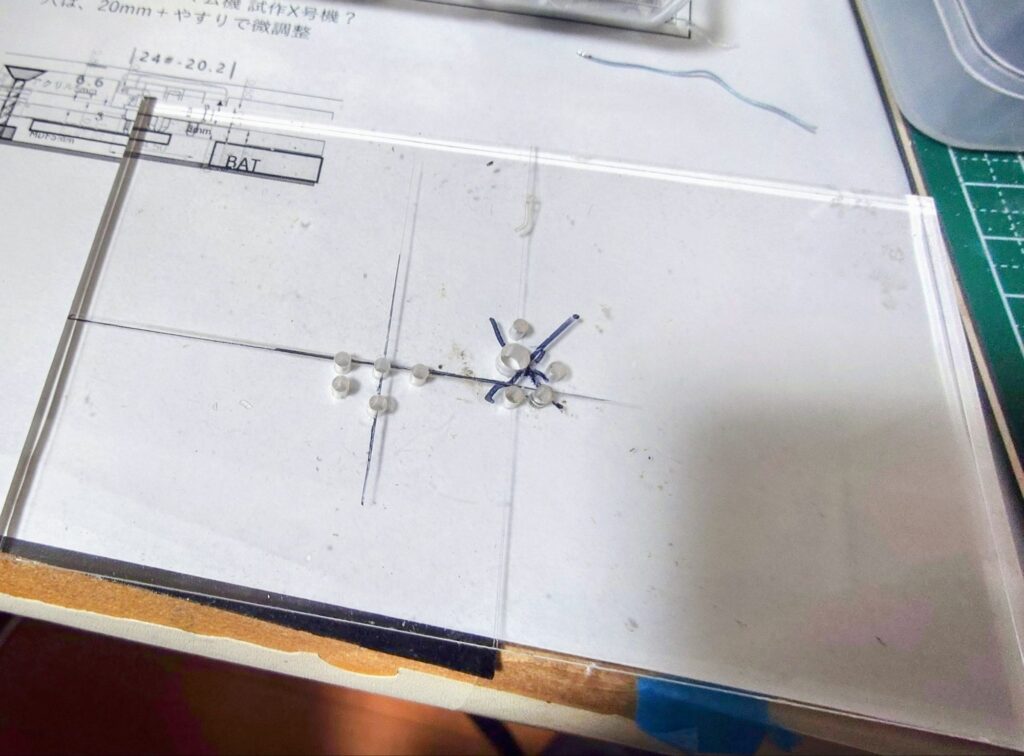
To drill the key switch pin and guide-post holes, I used a printed template to drill 2mm guide holes into an acrylic sheet to create a drilling jig. Using an M2 screw through the pre-drilled center hole as an alignment pin, I drilled out the remaining holes along this jig. The center hole was later widened to 3mm.
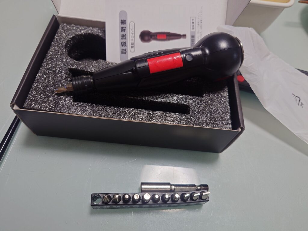
To keep the work nimble, I used a compact, screwdriver-sized electric drill. I bought it specifically for this project, and it made the job immensely easier.
White Primer, Soulful Red, and Wiring That Doubles as Geometric Art
The 3mm MDF board acting as the internal substrate (salvaged from a Seria clipboard) received a special base coat beforehand.
Rather than painting directly onto raw MDF, to make the colors really pop,a coat of white plastic primer-surfacerwas sprayed across the entire board. Over that, as our vibrant base color,a coat of redwas applied. For this red, I selected the deep, lustrous"Soulful Red"—the exact paint color of my beloved ND Mazda Miata (Roadster).
And here is where the build's proudest feature comes to life: merging wiring seamlessly into graphic design.
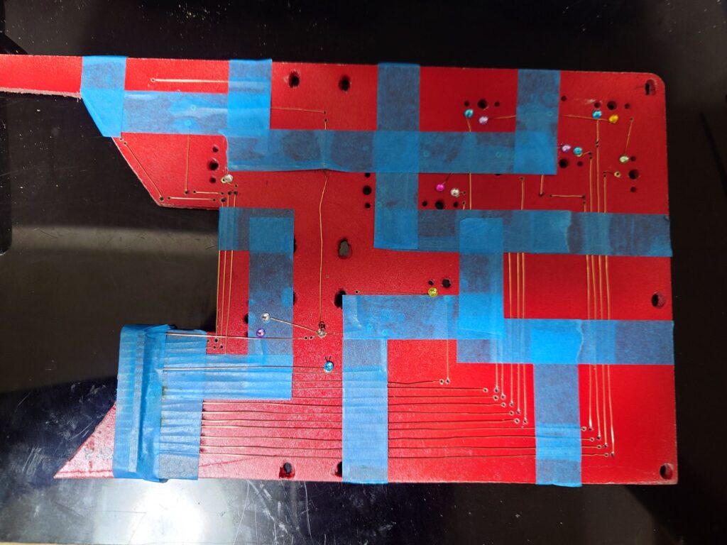
Using the micro-holes drilled per the Excel blueprint, I routed 0.32mm magnet wire in taut, laser-straight lines. The straight runs of blue masking tape securing the wires double asthe masking lines for a Tomoyasu Hotei-inspired geometric patternthat defines the final visual.
By spraying another coat of Soulful Red over this setup, peeling off the tape reveals subtle shade contrasts and depth against the base layer, causing a crisp geometric pattern to emerge naturally.
The "Twin Micro-Hole Anchor": Bending Wire Runs at Sharp Right Angles
To produce the crisp geometric artwork mapped out in the blueprint, the magnet wires had to turn at sharp 90-degree angles. But bending wire freehand inevitably leaves the corners lifting and rounded.
To solve this,I drilled two small 1.5mm holes right next to each other at every right-angle corner, threading the magnet wire up from below and back down through the second hole to stitch it firmly in place.This proprietary anchoring technique keeps the wire taut and locks in pristine, razor-sharp 90-degree corners.
When viewed through the clear acrylic top, the subtle metallic sheen of the brass-toned magnet wire and the intentionally aligned masking lines stand out strikingly against the rich Soulful Red backdrop.It is a wiring system that achieves genuine functional beauty, harmonizing wire retention and paint masking into one cohesive design.That was the ultimate goal.
Crimping into Brass Sleeves & Masking with 100-Yen Craft Stickers
The magnet wires routed along these aesthetic tracks were now ready to connect to each button's key switch pins. This is where our batch-produced ~3mm brass tube sleeves proved their worth.
Because the MDF holes and brass sleeves have a tight interference fit, all it takes is sliding the flame-stripped magnet wire into the hole and pressing the brass sleeve down over it. The wire is clamped firmly against the switch pin inside the gap. Since it's completely solderless, there is zero risk of heat-damaging the low-profile switches.
The Brass Tube Masking Trick
Next, we needed to spray another finish coat of Soulful Red. But if sprayed as-is, paint would seep into the brass tube openings—the critical electrical contact points for the switch pins—causing continuity failures.
To prevent this,I picked up a sheet of small decorative craft stickers from a 100-yen shop (Seria)and applied one over the head of each brass tube as a mask. Peeling these stickers off after painting not only kept paint out of the contacts, but also left the polished circular brass rims exposed like decorative metallic polka dots across the red surface.
[Disaster Strikes!] The 2.54mm Pitch Trap: MDF Snaps Along the Perforations!
Right then, the DIY gods decided to test my resolve with an unforgiving setback.
To accommodate the solderless crimp header, I drilled a straight line of 18 holes into the MDF board at the standard electronic component spacing of 2.54mm pitch.
With the wiring set, I pressed the 18-pin connector in and began plugging and unplugging it a few times to test continuity and check clearances. That's when it happened.
*SNAP...*
A sickening sound echoed across the workbench.
Drilling 18 consecutive holes in a straight line with a tight 2.54mm pitch into 3mm MDF had critically compromised the structural integrity of that section. The MDF simply couldn't handle the push-and-pull stresses of inserting and removing the connector, and the row of holesacted exactly like the tear-away perforations on a snack box,causing the board to snap cleanly in half right along the seam—a catastrophic collapse.
Because the button drilling method had gone so flawlessly, overlooking the structural limits of wood under such high hole density was a total blind spot.
Pivoting to Soldering & a Tenacious Full Recovery
I had been chasing the dream of an entirely solderless build, but that dream means nothing if the underlying board fractures along a perforation line. Putting stubborn pride aside, I returned to the core principle: "As long as it's electrically and physically secured, it works." Without hesitation, I pivoted to reliable soldering.
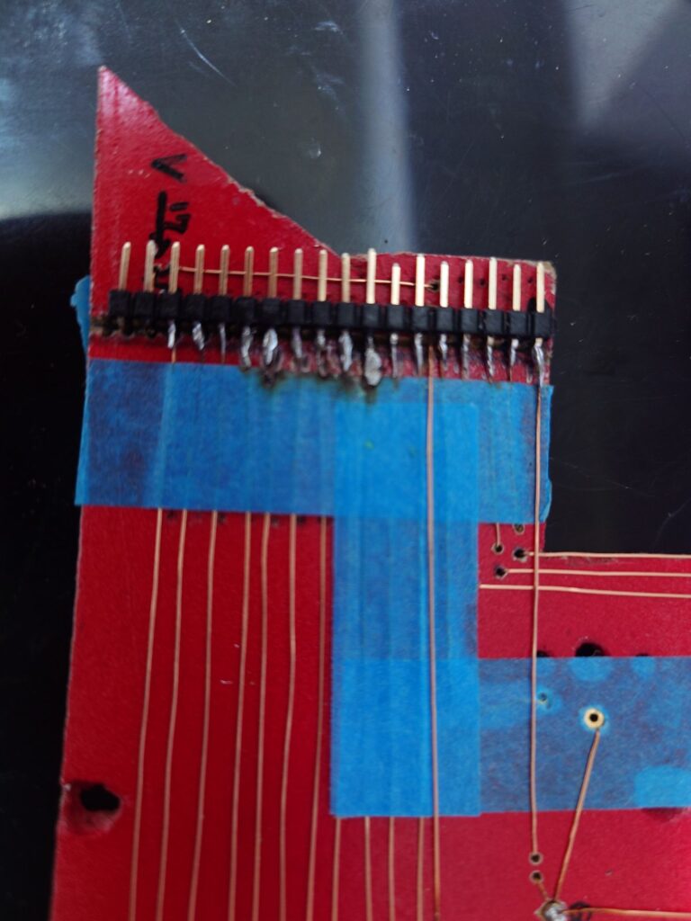
Additionally, I routed VCC from the far left, up over the top, across to the right side, and then fed it down.
Part 3 Wrap-Up: Functional Beauty Meets Chaos, with an Homage to Kikaider 01
With this, the most daunting hurdle of the entire project—the complete wiring phase—is officially finished.
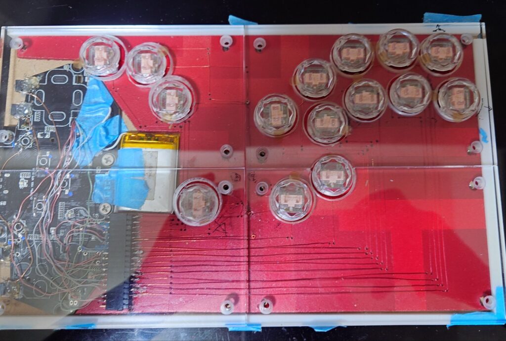
Viewed from the front through the clear acrylic top, the brass accents, subtle gleam of magnet wire, and calculated masking lines align in orderly perfection across the Soulful Red backdrop—"a striking functional beauty inspired by Tomoyasu Hotei's iconic guitar pattern".
Yet flip it over to the underside, and the harvested Apple cable's multicolored wires weave in an intricate tangle, exudingthe raw, chaotic vibe of the internal cybernetics in Kikaider 01.
It feels as though the donor board is held captive within the chassis, undergoing cybernetic modification as its soul is absorbed by the machine. This eerie yet stunning mechanical duality now lives inside a single enclosure—giving birth to a truly one-of-a-kind controller foundation.
In the upcoming Part 4,"Building Custom Side Buttons & Scratch-Building Spacer Pillars for Clearance"will be the main event. I'll unveil the full story behind the custom side-button mechanism crafted from Tamiya plastic square beams, delivering a crisp, responsive click.
And in Part 5, we'll dive into building an SOCD cleaner circuit using two standard 74HC132 logic ICs, along with the full proof of concept that conquered a tricky physical VCC contact issue. Stay tuned!