The Kayak Motorization Project: From Idea to Reality
 Admin
I’m going to share the journey of my kayak motorization project—from the initial daydreaming before I even bought the kayak, all the way to putting it into action.
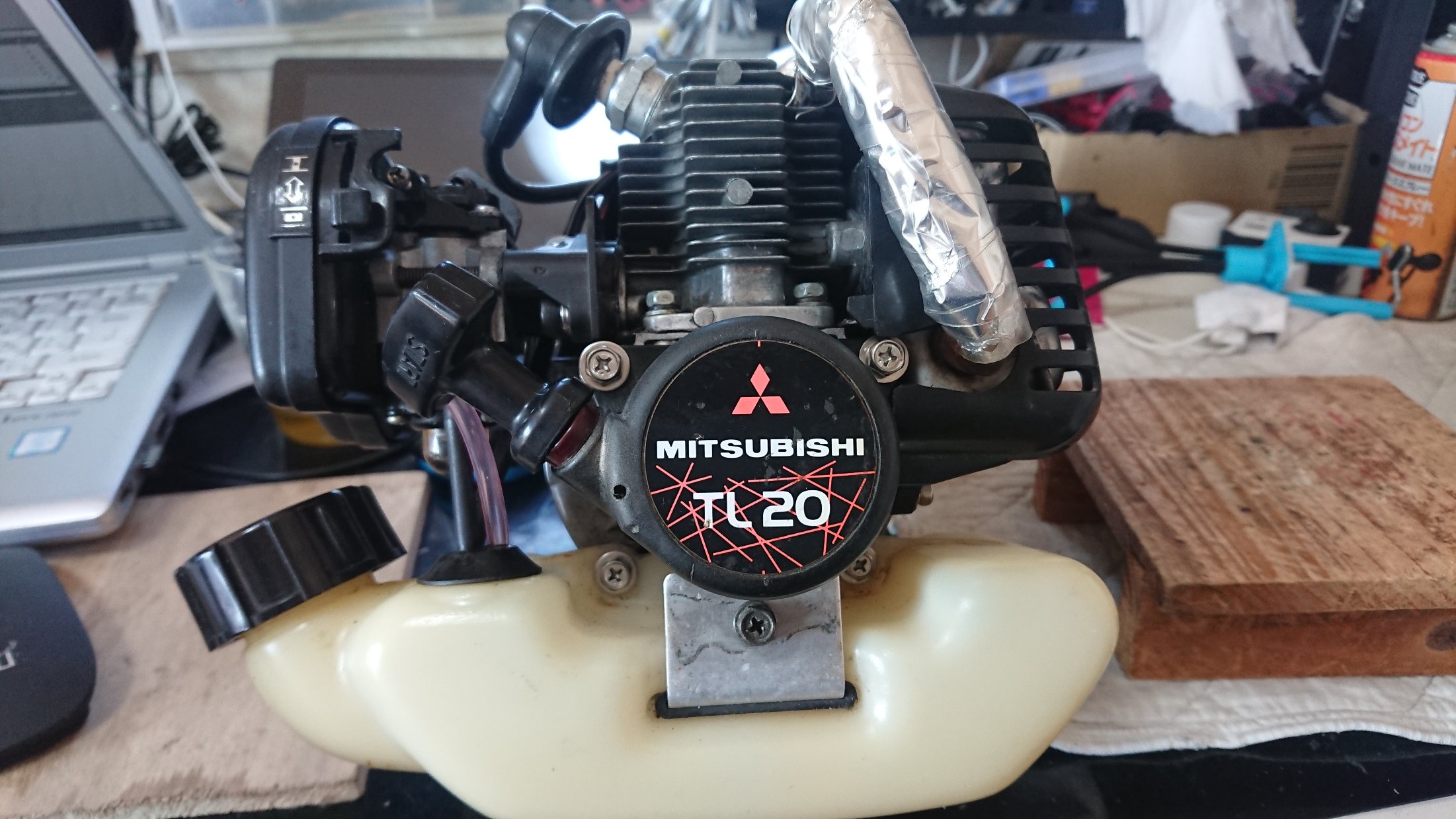
As I write this, I’ve already prototyped the connection and gear unit (reversal & reduction) for a grass-trimmer engine like the one in the photo, along with the propeller assembly. I still don't know how it will perform because I haven't tested the whole system yet. I've pushed ahead with the design and fabrication all at once up to this point. I was just one step away from finishing the whole setup—fixing the shaft pipe—when suddenly, out of nowhere... maybe because I didn't want it to end, I lost my motivation. Figuring this is a good excuse to pause, I’ll save that final part for later and record the background and work process before I forget everything.

The Inspiration
Even when paddling by hand, a light kayak glides smoothly, so adding a motor—even a small one—should give it some serious speed. Plus, I used to tinker with car engines, but I rarely got to work on them lately, so I really wanted to tinker with an engine again! Though these days, is electric the way to go? Plenty of people are doing it. Lately, paddling has gotten exhausting, and I'm totally beat from sunrise to noon. That's it! I'll add a motor!
I managed to revive a dead grass-trimmer engine given to me by a senior fisherman, which boosted my morale and really got the project moving.
Propulsion Methods
I'd been mulling over the propulsion method for a long time, initially torn between going electric or using a gas engine.
Electric or Gasoline Engine = I Love Gas Engines!
Pros of Electric
In today's SDGs-focused world, both cars and motorcycles are going electric. Electric tech is advancing rapidly, making it technologically fascinating. You can easily buy high-capacity lithium-ion batteries and heavy-duty motors on Amazon. There are also plenty of mechanical parts available, probably thanks to 3D printing hobbyists. With an electric motor, everything except the motor itself can be placed in the center of the boat, providing great balance. Even without building from scratch, it's easy to just mount an electric trolling motor and bring the controller to the front of your seat. Plus, it's quiet, so maybe fish won't notice you?
Cons of Electric
The batteries are insanely heavy. Standard batteries used by veteran bass fishermen require two 20kg units, which would probably sink a kayak. Lightweight options like lithium-ion batteries solve this, but they are still quite expensive.
Pros of Gasoline Engines
Having tinkered with motorcycles and cars for ages, tinkering with a gas engine just sounds like way more fun. Weight-wise, even with gasoline, it's lighter than an electrical setup, and the cruising range is longer. The sound is satisfying. It's wild... Okay, this is purely a matter of personal preference.
Cons of Gasoline Engines
They're noisy. For standard outboards, the rear overhang is heavy. The engine might fail to start. They rust. Maintenance is a pain.
The Conclusion
It’s as if my wish for "I love engines!" was granted when my senior fisherman friend gave me a broken grass-trimmer engine. I decided to use it to build my propulsion system. (Well, for now anyway. I'm designing it with future conversion to electric in the back of my mind.)
Propulsion Styles
As candidates for the propulsion style, I considered:
- Outboard Motor
- Long-Tail
- Short-Tail
Outboard Motor
An outboard motor looks something like this.
Are electric trolling motors used for bass fishing boats considered outboards too? (I always think that terms in the bass fishing industry don't really describe what things are. Calling it an "electric motor"—which literally translates to "electric power machine"—doesn't tell you if it belongs to a car or a motorcycle.)
Outboard motors are mounted with an overhang at the stern of the boat. Since they're easy to attach, license-free 2-horsepower outboards or cheap Chinese imports are readily and affordably available. However, on a relatively small boat like a kayak, a gas outboard creates terrible weight balance, making the stern sink. While some people add outriggers to compensate, I hate that because it sacrifices the kayak's agility and compactness! Would a smaller unit like a JMO motor still be okay? Even then, having around 5kg hanging off the rear overhang, even if it doesn't sink, wrecks the balance.
Just as a front-midship longitudinal engine FR car layout (essentially a Roadster) is the ultimate setup for cars, a super-heavy rear overhang layout (like a Porsche, VW Beetle, or older generation cars) is definitely something I want to avoid!
Long-Tail
A long-tail boat is a wild marine propulsion system used in Southeast Asia (Thailand, I think?) that utilizes a longitudinal engine, likely from an old FR car, with the propeller shaft extending straight out of the boat into the water, ending in a propeller! People probably started doing this because specialized outboards were too expensive to buy, and the tech is simple. I didn't know about this until I started looking into this concept (maybe about 5 years ago?), but apparently, they're used daily and even serve as tourist attractions. When I looked at one long ago, there was an amazing setup running on a V6 engine.
With this design, you don't get that heavy rear overhang, and it seemed easy enough to build using parts like a grass-trimmer shaft. I've actually seen Japanese people doing it on YouTube.
It’s a great candidate, but since the shaft goes straight into the seawater, I worry about waterproofing. They probably pack it full of grease, but it's hardly eco-friendly. Plus, it makes the total length longer, which hurts the kayak's maneuverability and portability. I couldn't reach an immediate conclusion. After considering various implementation methods, I am currently working on something closer to the short-tail setup described next. (Though I might end up trying a long-tail in the future.)
Short-Tail
This is the counterpart to the long-tail system. A quick Google search today doesn't bring up many results, so it must be pretty niche. The engine is mounted longitudinally, and its power is temporarily transferred underwater via a chain or pulley to spin the propeller, shortening the overall length.
Evaluating Implementation Methods for Each Style
Evaluating the Engine Long-Tail Approach
The grass trimmer I was given is a backpack-style unit, consisting of an engine + a flexible, bendy shaft + an adapter + a long shaft + gears + a cutting blade.
Test Grass Cutting and Fuel Tuning
I came out to my usual spot at the bass fishing dam to do some test grass cutting and fuel tuning. Since I wasn't feeling particularly motivated and arrived a …

Converting the Bendy Shaft into a Straight Long-Tail

I wanted to connect a straight shaft from the engine into the water, but this trimmer engine comes with a curved shaft. Up until now, I thought I'd either have to connect a straight shaft to the existing setup or build one from scratch. The shaft emerging right after the clutch from the engine side connects with a 7mm square tip. In contrast, the connection on the shaft side features a gear-like multi-groove pattern. Connecting the original parts would require machining the mismatched shaft connection shapes, which is a pain. It's easier to build from scratch.
The flexible pipe shaft has a 7mm square opening, and since it was originally attached to the engine side, no modification is needed there. The other end is also a 7mm square, which is easy to work with—nice! But you can't use this flexible shaft for a long-tail setup. The idea that flashed through my mind at this point was: why not just shove the flexible shaft inside a 34mm inner-diameter round pipe to make it rigid?
Conceiving the Propeller Assembly

Next, I considered the design of the propeller section. The prop is an aluminum 2-horsepower boat propeller I picked up quite a while ago for about 1,600 yen. It's pretty heavy! Also, being meant for a 2HP motor, it's way too big for a kayak. Furthermore, a 20cc grass-trimmer engine might not have enough torque to spin it. That means gear reduction is necessary, though I hadn't factored that in at this stage.
I originally wrote "brass" here for the 10mm pin, but since brass rusts, I decided on aluminum instead. I'd been brainstorming concepts for a while, like sticking it through and securing it with a pin. I was figuring out how to construct the connection between the gear-side shaft tip of the flexible shaft and the propeller-side receiver. For an amateur designer, having off-the-shelf parts or easy-to-machine materials is key. I can machine a 7mm square male end, but as an amateur, I can't machine a female end. No final conclusion reached here yet.
Reverse Propeller Rotation → Using a Gear
On the right-hand page of my notes, a sudden thought struck me: "The propeller spins in reverse." I like to jot down sudden inspirations like this in my notebook and work them out. If I don't reorganize and rewrite everything later, it gets confusing, so I'm hoping to neatly compile and write it all out on this blog.
What do I mean by "reverse propeller rotation"? Looking toward the propeller direction, a grass-trimmer engine rotates clockwise. While this is convenient when fabricating custom shaft components because standard right-hand thread screws can be used, for some reason, the 2-horsepower marine industry seems oblivious to this, or perhaps they have a reason? It seems standard practice to insert a single gear into a clockwise engine to reverse it, meaning the propeller spins in the opposite direction. Standard forward rotation is defined as clockwise when looking at the propeller from the front. In screw coordinate systems, this equals counter-clockwise = reverse rotation. Therefore, I need to reverse the rotation direction. My solution for this was to attach the gear located right before the cutting blade at the end of the grass trimmer. Inserting a single gear (two gears total in the mesh) reverses the rotation direction. Alternative methods would include buying a large model-airplane propeller or making one from scratch... But I want to use what I have on hand, and that 2HP engine component I have is the most common and easiest to source in the future.

Additionally, adding a gear makes mounting the propeller super easy. Drilling a hole in the bolt that secures the grass-trimmer blade looks like it will do the trick, completely solving the previously mentioned headache of not being able to machine a 7mm square female socket.
In the middle of the drawing on the left page, where I wrote "■ Overview," I sketched the overall grass-trimmer shaft and the shape of the connection parts. For some reason, every single one of them is different. You'd normally think that if you remove the flexible shaft, a straight shaft would attach directly to the engine. Why don't they sell them with that kind of modularity? I just don't get the reasoning. And if I don't need the flexible shaft, should I just buy a new grass trimmer? Though it doesn't look like they sell shafts that fit on their own.
Here, I concluded that to join the 7mm square male end past the flexible shaft and the 5mm square female end of the gear unit, I just need to shave down the 7mm shaft to 5mm. It's a relatively easy modification, and thanks to this, I eliminated that tricky gear-shaped connection problem I ran into earlier!
At the very bottom of the right page, I drew a curvy sketch. This was the idea: rather than needing a long-tail length, why not actually use the flexible shaft, bend it, and route it straight down into the seawater?

To fix it in place, I'd route it through a 45-degree PVC rain gutter pipe to hold the curve.
Subsequent brainstorming revealed some drawbacks, and I ultimately shelved this long-tail project.
- The flexible shaft is extremely heavy.
- Putting grass-trimmer gears in seawater will cause the gears and bearings to rust. Impossible. Do a full overhaul every single time?
...The conclusion I reached:Parts submerged in seawater should be made of plastic/rubber components = pulleys.
= In other words, a short-tail design.
Evaluating the Engine Short-Tail Approach
To prevent rusting on parts submerged in seawater...Make them out of plastic/rubber parts = pulleys.
With that, I changed direction. As shown in the sketch below, I finalized the overview of the system moving toward its final form. This concept of using a pulley mechanism on the propeller side stuck with me all the way to the end.

Pulleys don't reverse rotation on their own. Researching online, it seems there are ways to reverse rotation by crossing a belt on pulleys, but that sounds like a nightmare with friction and tensioning issues, so I'm skipping it. Therefore, I still need to insert a single gear, which also helps with gear reduction. My solution was to mount the grass-trimmer gear at the upper deck pulley section ahead of the propeller pulley, angled when viewed from top-down. This gear naturally has a 30-degree angle to point the cutting blade toward the ground, but thanks to the flexibility of rubber pulleys, I can introduce a twist to transmit power down to the lower pulley.
The System I Chose
My requirements were: no rear overhang for the propulsion unit, no rust, and since I'm using a high-revving 2-stroke grass-trimmer engine (which has ridiculously low torque at low RPM), I needed massive gear reduction. Keeping all that in mind, I settled on this configuration.
I combined the long-tail advantage of placing heavy components in the center of the boat with the short-tail propeller setup to solve the long-shaft drawback.

This is a side-view diagram. The rounded object on the left is the grass-trimmer engine, which sits just behind the seat at the rear of the kayak. From there, power is transmitted through the reduction & reversal gear to a shaft, which then transfers power down to the propeller unit in the water via the rear pulley. I'll write more about the detailed design philosophy later.
This drawing was the final sketch of the overall system, and at that point, my theme was "how to prevent engine vibrations from transmitting to the rear." The conclusion was to connect each major component loosely. The idea was to use a "Uni-joy" = "Universal Joint" for a loose connection, securing everything to a framework positioned underneath. However, right now I'm still debating whether I even need a universal joint, since I want to simplify things and prioritize ease of maintenance.
I stated the conclusion at the beginning, but this is the result of 5 years of daydreaming and 1 month of serious deliberation. I'd like to keep writing about the long-tail ideas I abandoned along the way and how I got to this point. I'll also share how I figured out machining methods despite being an amateur without specialized machine tools.

