DIY Motorized Kayak Project: Detailed Design Concepts
 Admin
Let's dive into the detailed design concepts for each section.
As a quick refresher, here is the rough layout sketch I shared in my last post:

Gear Unit - Shaft Unit - Propeller Unit
That's the basic breakdown. Now, let's break down the design for each of these three major components.
The Propeller Unit
Propeller Mechanism

The propeller section will be built around a 5mm or 10mm thick aluminum base plate, housing two pulleys and the custom propeller we designed earlier. Since the main requirement is just keeping the prop securely held, I might reduce weight and cut down on rigidity by thinning the upper connection or linking things with pipes. The biggest hurdle is the bearings. For parts above the waterline, miniature bearings are the obvious choice, but since the propeller sits directly in seawater, they're completely out of the question. While rust-free options like ceramic bearings exist, I also spotted items labeled "resin bearings" that look like simple plastic tubes at my local Handsman hardware store. I'm planning to use one of those resin pipes for the bearing.

Ultimately, the layout will feature an aluminum base plate holding just the propeller mechanism, with a support structure at the back. This support will be sized to press right up against the trailing edge of the kayak's keel.
The upper section won't be submerged, but pulley belt spray will still drip down. To make washing and maintenance easy, the connection between this part and the long shaft needs to be quick-disassemble. A simpler structure is definitely better here. Is this mounting method the right way to go? I'll need to double-check how easy it is to detach.
Universal joints are easy to get hold of, but they have a complex mechanical structure and look prone to rust. Maintenance would be a nightmare, so I've decided to skip them.
The upper bearing will be tucked inside a pipe to shield it from splashing seawater.

I'm planning to secure the bearing area using snap rings. You can cut your own grooves by mounting a shaft in a drill and pressing a thin metal-cutting saw blade against it. Clip rings come in both iron and stainless steel, and stainless shouldn't rust—just look at the shiny hardware on boats and pier mooring posts. That said, if they experience a lot of friction, they might rust before a protective oxide layer can form.
Transmitting Thrust

The pushing force of the propeller is bound to be immense. We need a rigid structure at the prop base to handle that load, so I'm planning to design it so that the center of the propeller braces directly against the back of the keel. The exact dimensions are based on physical measurements of the actual parts. Propeller component sizes, shaft hole dimensions, and more specific numbers will probably show up in the upcoming fabrication post. I already made a quick prototype of the prop base out of wood to test the waters, and it seems promising, though I haven't built the final functional prototype yet. Still debating whether to go with a 5mm or 10mm thick base plate.
The Shaft Unit
The shaft unit has very few challenges, so I haven't thought too deeply about it. For now, it'll simply use a 5mm stainless steel shaft supported by two 950 bearings, housed inside an aluminum pipe (9mm inner diameter / 11mm outer diameter) left over from an old project. A thicker shaft would feel sturdier, but this one is rigid enough that it shouldn't bend. As for the bearings, I cleaned up some old 850 and 950 bearings salvaged from a past fishing reel modification and used them for a dry-fit assembly. Some don't spin super smoothly, so I plan to swap them out in the final build.
The Gear Unit
The gear section is pretty intricate, and honestly, I'm having a blast designing it.
Why We Need Gears and Reduction Ratios
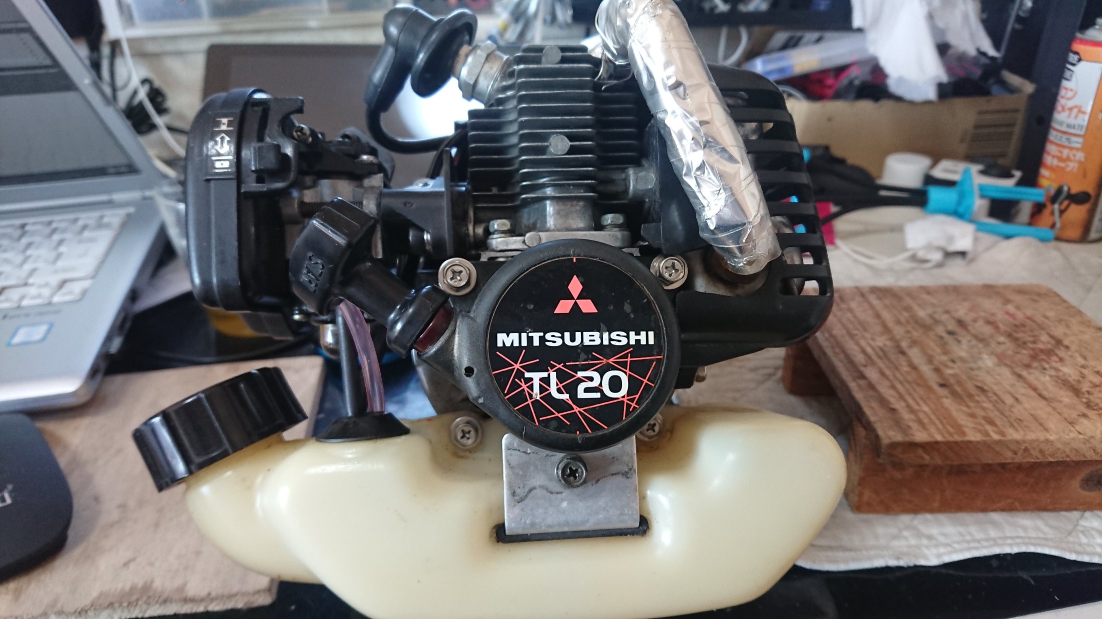
Brushcutter engines are two-stroke and high-revving, which means they seem to have zero torque at low RPMs. I've never actually ridden a two-stroke motorcycle, but I hear they idle around 2,000 RPM and rev really high. Taking off apparently requires extra technique—revving even higher and slipping the clutch a lot compared to a four-stroke. On the flip side, once the clutch fully engages past the slip zone, you get hit with this explosive, rocket-like acceleration. (Man... I kinda want a 125cc two-stroke bike.) On a car or motorcycle, skilled riding lets you constantly stay in the high-torque power band to blast around, which is half the fun. But in a boat without a transmission, that power delivery would be a nightmare to handle. So, I did some research.
Brushcutter Clutch Engagement Speed is 4,000 RPM
Brushcutters use an automatic centrifugal clutch. I've torn these down completely, so I understand the mechanism well: springs pull the clutch shoes inward, and as the engine revs up, centrifugal force overcomes the springs, pushing the shoes outward. They make frictional contact with the inner wall of a funnel-shaped outer housing, slipping slightly as they start to spin it. Those springs are way stronger than you'd think—you can't pull them apart with your bare hands.
While using a brushcutter, I realized this clutch plays a crucial role. If you get careless and jam the blade into a tree, the engine occasionally stalls out, but I suspect the clutch slips just enough to protect both the operator and the engine from damage. Instead of being locked solid, it slips until the speeds match up when under load. This insight heavily influenced my subsequent gear mechanism design.
Looking up the clutch engagement speed for a brushcutter (found in the manufacturer's catalog), I learned it kicks in at 4,000 RPM, topping out around 10,000 RPM. Typical two-stroke characteristics, much like a motorcycle. Brushcutters get away with this because they rev up freely in the open air with no load. If you slap that straight onto a boat without a gear reduction, it would instantly churn up water with aggressive, peaky force. Once moving, it might be manageable, but the sudden shock would likely wreck my custom-built components. Based on those numbers, a gear reduction is definitely necessary.
Usable RPM Range After Clutch Engagement: 4,000 to 10,000 RPM
Possible Solutions
- Gear reduction. Cut it in half? Down to 1/4? 1/8?
- Implement a slip function to build up speed smoothly (like feathering a clutch).
- Use a smaller propeller.
- Lower the clutch engagement RPM by using weaker springs.
Regarding downsizing the prop, I watched a YouTube channel where someone built a DIY brushcutter long-tail motor, and because they couldn't get the RPMs high enough, they kept shrinking the propeller. Because of that, I'm also looking into model-making props, some of which get close to 70mm in diameter.
Lowering the clutch engagement speed was an option I initially wanted to try, but thinking about it now, it would probably kill the engine's torque, causing it to stall the moment the clutch engages.
Reduction Ratios and Usable RPM
| 減速比 | 使える回転数域[rpm] |
| x1 | 4000-10000 |
| x1/2 | 2000-5000 |
| x1/4 | 1000-2500 |
| x1/8 | 500-1250 |
Where should we aim? A lower bottom-end RPM would be nice—maybe 500 RPM—but that drags the top end down too. Tricky. How fast does a kayak actually go with a standard 2-horse motor running its prop at 1,250 RPM? Maybe I should just build it and see what happens.
What About Standard 2-Horsepower Outboards?
I did a quick check on the RPMs of standard 2HP outboard engines (looking at idle to max RPM, not clutch engagement):
- Tohatsu: 1,300 to 5,500 RPM → Prop RPM: 500 to 2,000 RPM
- Honda BF2: 2,000 to 5,500 RPM → Prop RPM: 800 to 2,000 RPM
Both are four-strokes, of course. Are there even two-stroke outboards left? Makes sense, though—aside from being easier to handle, two-strokes practically spew oil straight into the ocean. Their gear ratio is around 2.42:1, which is what they use to step things down. Oh, so an idle prop speed of 500 sounds about right. A 1/8 reduction? That's a massive gear drop. The top end would drop to around 1,250 RPM, which is about half, but for pushing a narrow, low-resistance kayak, half power should be plenty. If I applied similar torque, it would probably launch like a hydroplane boat.
Gear Placement: Transaxle Layout vs. Unitized Design

My original idea was to pack the gears right next to the pulley. Grouping the mechanism near the pulley keeps things compact and user-friendly. Having the gears situated at the rear is basically what cars call a transaxle setup—like the Nissan GT-R? It's a layout used in only a handful of high-end sports cars.
However, if I do that, the 5mm shaft enclosed in a skinny pipe would have to spin at screaming speeds of 10,000 RPM. Terrifying. I want to step down the RPMs early on so that all my custom-made parts rotate at a leisurely pace. That's why I decided to place the gear unit up by the engine, as shown in the top diagram. This split the project into a three-part configuration: Gear Unit, Shaft Unit, and Propeller Unit. This modular setup lets me swap out just the gear unit to test different configurations. Plus, if I ever want to swap the gas engine for an electric motor, I can just adapt the gear combo to match.
How to Implement the Gears: Baitcast Reel Gears, Spinning Reel Gears, R/C Gears
For the gears themselves, I originally planned to use some baitcasting reel gears I had lying around. They offered a 7:1 ratio across two gears, which felt just about right. Finding that they fit so perfectly got me super hyped and really kicked this project into gear.

This sketch still shows the transaxle layout. The first gear is where the spool shaft inserts, and the second gear sits where the handle normally goes. I also considered whether I could repurpose the reel's drag mechanism to handle the brutal engagement shock of the two-stroke engine. While using an intact reel body crossed my mind, modifying it would be a pain, so I concluded I'd have to fabricate the housing from scratch. But how on earth would I adjust the drag mechanism then?

I eventually ditched the drag idea and refined the design further. However, as I brainstormed other ways to achieve that necessary "slipping" action, this concept evolved into something entirely different and was dropped.
Baitcast reel gears are made of brass, which makes them seem fragile and prone to corrosion. Reel manufacturers really don't spend much money on materials, do they? Even high-end models like the Stella don't use stainless steel. Manufacturers must be making a killing. That lingering doubt pushed me to check out R/C car gears instead. What do they call standard Tamiya R/C gears again? The primary gear was metal and looked tough, and they had tons of variations. But the mounting hole was just over 3mm, and since my design standardizes everything around a 5mm shaft, I'd have to bore out the holes. Meanwhile, the secondary gears were only available in plastic. Plastic feels too easy to strip. I hesitated, but ultimately left the hobby shop empty-handed. Amazon did have some monster truck gears with 5mm holes that looked usable, though.
I also looked into spinning reel gears, but placing them on the engine side would alter the shaft angle and throw off the symmetry between the shaft and the engine, so I scrapped that idea. If I were willing to tolerate high-speed shafts, a transaxle layout would balance the weight nicely—which would actually work great if I ever switched the propeller end from pulleys to a true shaft-drive system.
Friction Drive System
Wondering if there was a way to cushion the shock of the two-stroke clutch engagement, I stumbled across a mechanical design concept called a friction drive. The basic idea is to press wheels together like gears, transmitting rotation purely through frictional force.

This was it! Using the pulley wheels and O-rings I was already playing with seemed like a viable way to pull this off. Around that time, I noticed my local Handsman hardware store stocked an incredible variety of O-rings. Since my custom pulley belts lacked the tensile strength I needed, I was scheming to use these O-rings instead. When I actually tested an O-ring paired with a pulley wheel, it was a match made in heaven.
Unlike traditional gears that lock teeth, friction drives slip when speeds don't match—acting as an automatic slip clutch! Once acceleration catches up and the speeds synchronize, they rotate together. What a wonderfully forgiving connection! That kind of slip would render a car or motorcycle undrivable, but for a boat, it's an absolute game-changer.

For the smaller gear side, I'll use two smaller O-rings on the shaft. Unlike pulleys, this reverses the spin direction. That gives me both directional reversal and gear reduction, but since the initial reduction ratio is a bit low, the final design will use a second door roller pulley to step it down further. Due to space constraints, going too small ruins the balance, but picking sweet-spot sizes gives me a 3.5x reduction on the first stage and a 1.5x reduction on the second pulley stage, totaling a 5.25x reduction. It falls a bit short of my initial 8x target, but since it provides built-in slip, I'll give it a shot. If it fails, I can always add another reduction stage or gear it down further at the propeller.
The big questions are: Can it handle 10,000 RPM? How bad will O-ring wear be? Will it even last a single day out on the water?

